
I “completed” my build last weekend and managed to take pictures somewhat inconsistently along the way which I will show you here. I successfully tested the video equipment, configured the ESC and flight controller software, and performed a couple test flights in my backyard. However, the tinkering is not over yet… more on that later. For now, on to the build! (If you want a TL;DR version, scroll to the bottom for a time lapse video that covers almost 18 hours of assembly.)
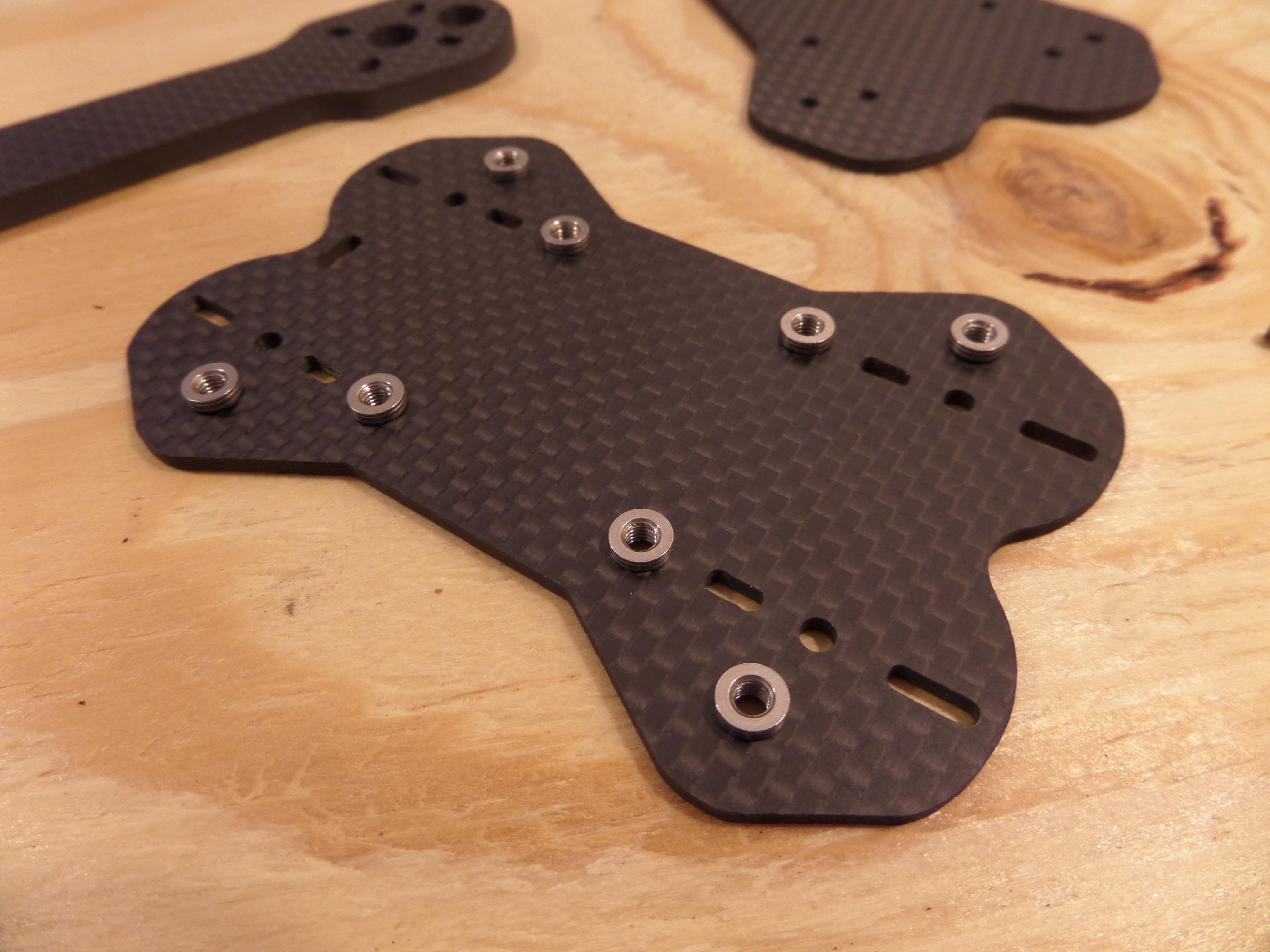
Step 1: insert recessed nuts into carbon fiber. NOT easy until I learned the trick…
I began by assembling the bottom of the frame. These nuts are supposed to be friction mounted inside holes in the bottom of the frame, which turned out to be difficult at first… they were impossible to just press into the frame with my bare hands, and using tools like pliers or a vice is a no-no since the carbon fiber could be damaged. I got them started with my bare hands, then tried to attach one of the arms and the other bottom plate. That turned out to be a waste of an hour and I had to take it apart and basically start over in order to get these recessed all the way first. I ended up just running a screw up through from the other side and used it to pull the nuts down into the frame. By doing so I also learned that it is in fact possible to strip a steel hex head screw. Hopefully this wasn’t an indicator of things to come!
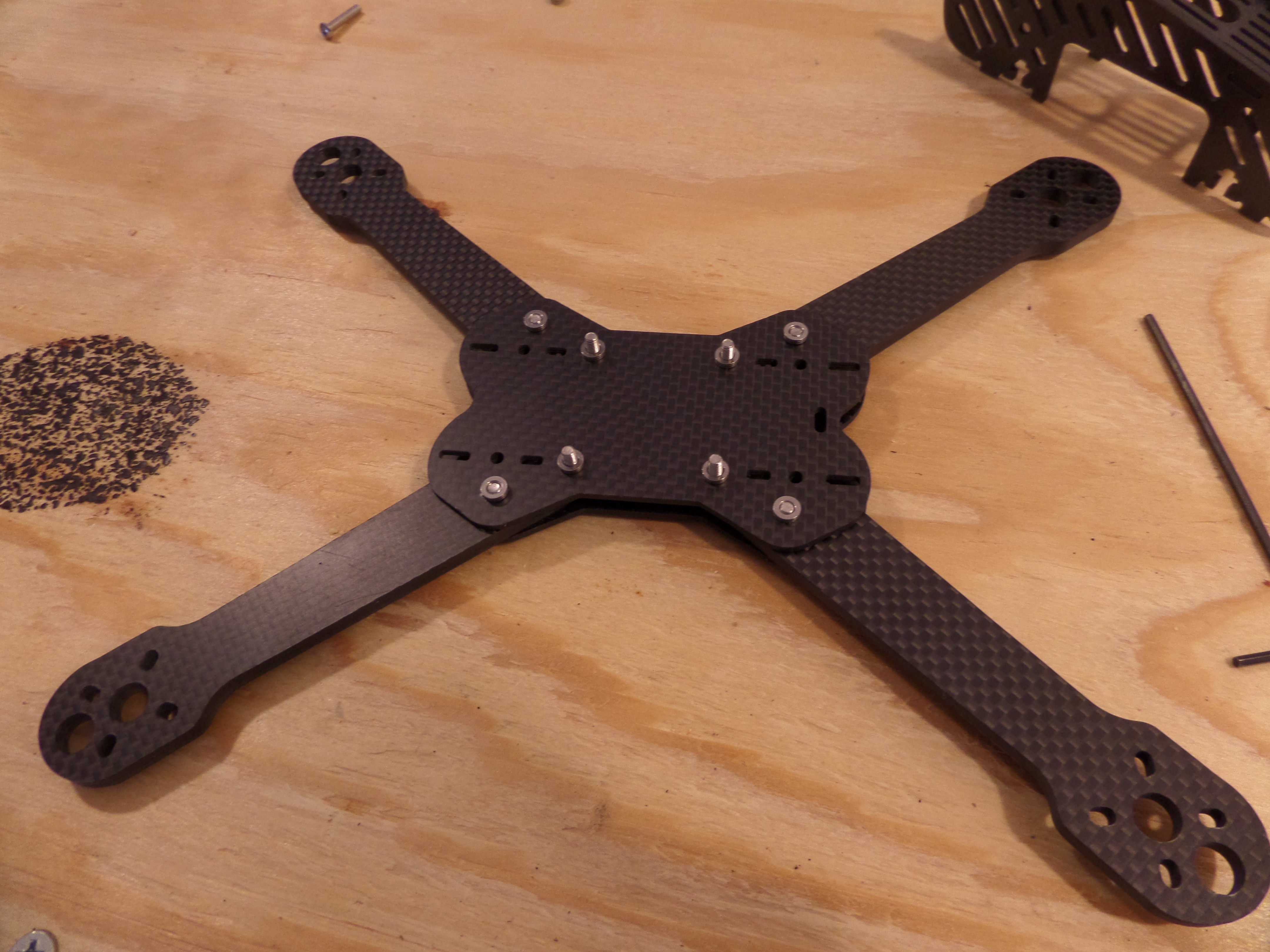
Arms attached to bottom plates!
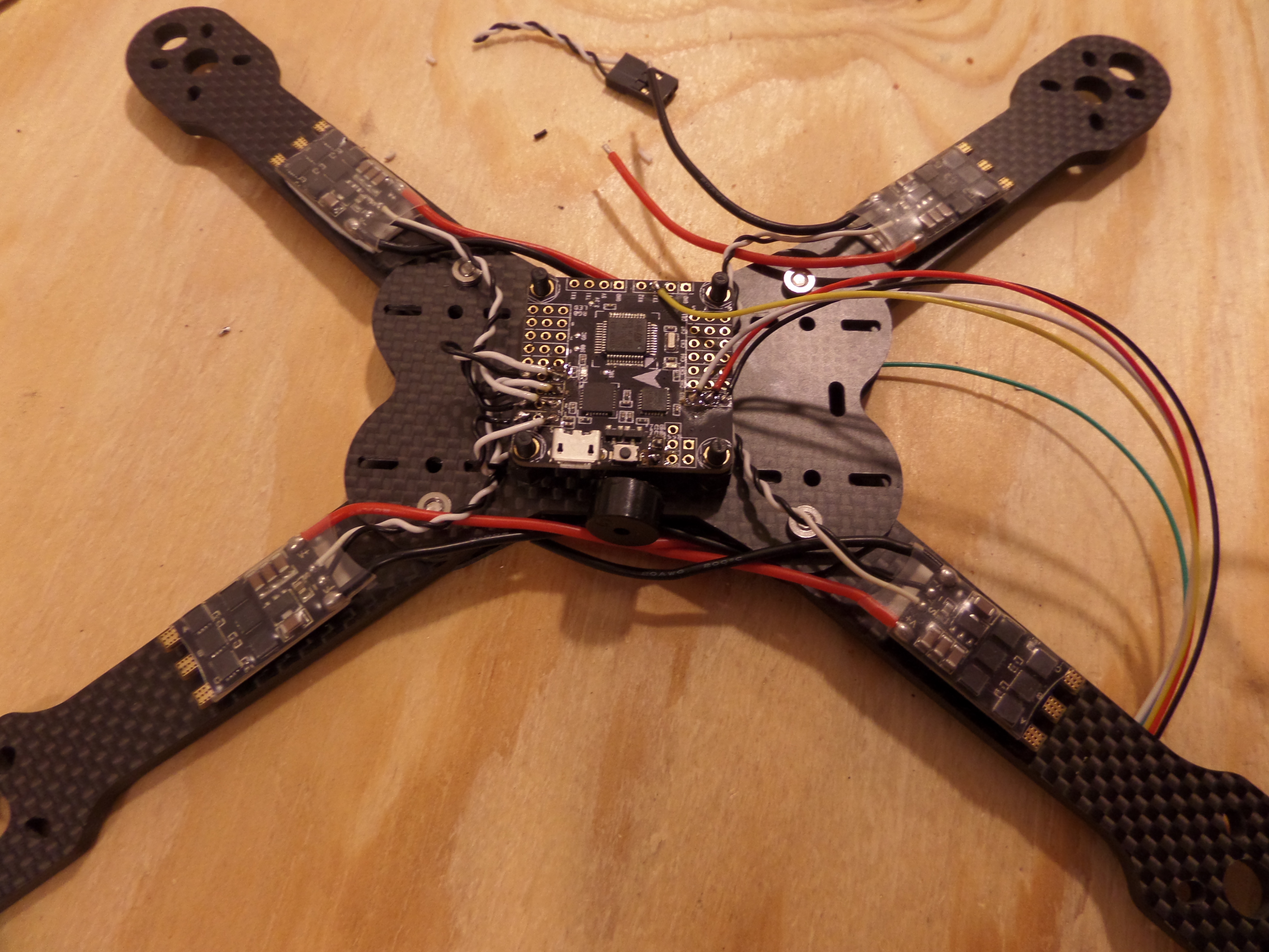
I finally got the base assembled with the four central screws ready to mount the core electronic pieces. From here I switched over to the electrical work which is the most complicated part. I have never shorted out the electrical system in any of my previous projects, but I was still diligent in checking all my connections with a multimeter.
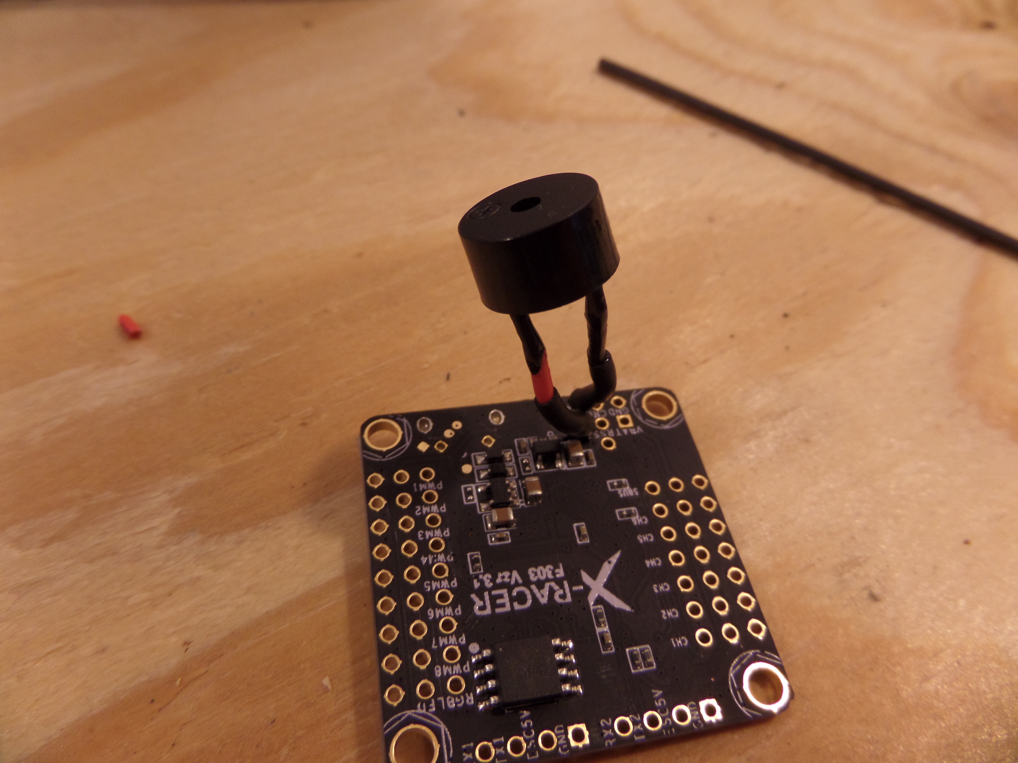
Adding a 5V buzzer to the flight controller
This flight controller (FC) has output pads for a buzzer, and I just happened to have a couple of them lying around, so I wired this one up. The FC will use this to beep in certain situations like when the copter is armed or disarmed. I’ll also use a radio channel to be able to manually turn on the beeper–that will be useful in a situation in which I might crash in something like a field of tall grass and need help finding the copter.
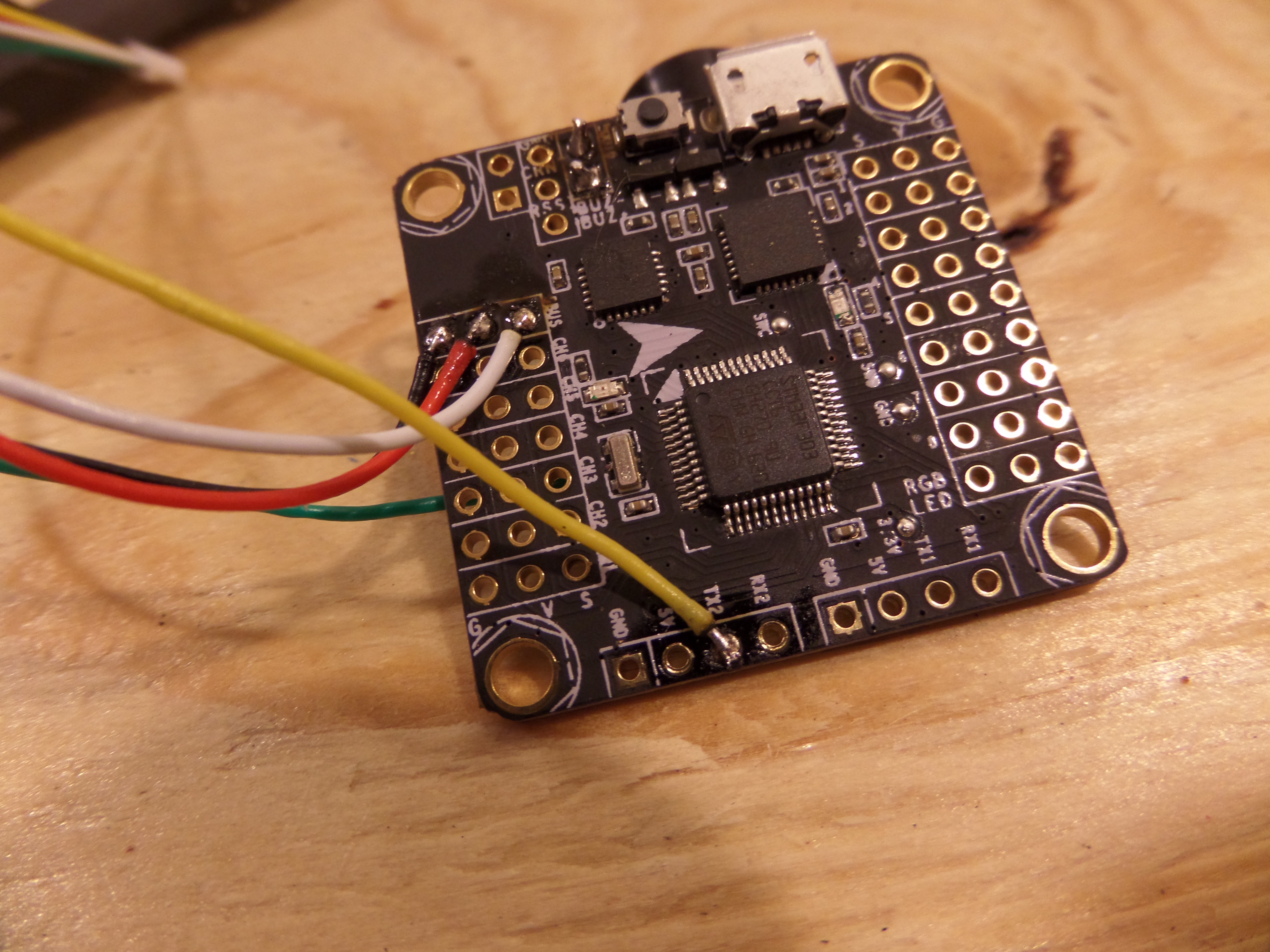
Connecting leads for the radio receiver
Next was connecting the radio receiver. Red and black are 5V and ground, white is for the SBUS connection that carries the radio commands, and the yellow is an optional connection that will allow the FC to transmit telemetry back to the receiver, which will forward it to my radio controller. The green wire is used for a combined PWM signal that could be used in place of SBUS. I just cut the wire off since I won’t use it.
ESCs mounted – attaching signal wires
Here is where things start to get complicated. I attached the ESCs to the arms with some double sided foam mounting tape. The next step was to solder their signal wires to the appropriate pads on the FC. This is where I really had to start taking the frame design into account. The canopy allows a pretty narrow opening for wires to enter the core, so I had to cut the wires down to the right lengths while still allowing some slack to allow partial disassembly for later service.
The signal wires are all on adjacent pads and I was a little worried about the possibility of a short, especially since for this build I just soldered the wires directly to the top of the holes instead of running them through first. To compensate for that risk I used a new product that I haven’t used before called liquid electrical tape, which is exactly what it sounds like. I just brushed a layer onto the at-risk area and a few minutes later it looked like it had all been shrink wrapped. Pretty handy stuff! Provided you abide by the FLAMMABLE VAPORS, FATAL IF SWALLOWED warnings. (Fast forward to that night when I was trying to wash off the liquid tape and solder flux that had accumulated on my hands–I couldn’t find any rubbing alcohol, so I used vodka. It makes a decent solvent!)
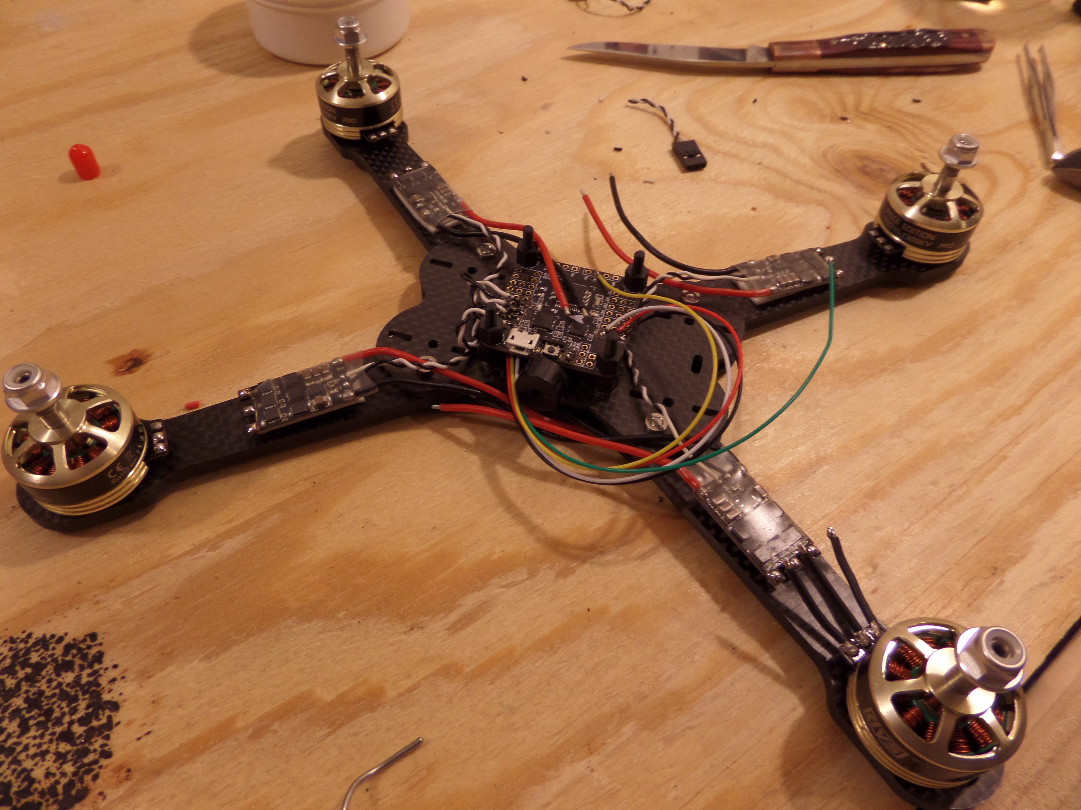
Mounting the motors
I’m trying another new technique with this build, which is to “soft mount” the motors. If you are trying to get a multi-rotor helicopter like this to fly well, vibration is your worst enemy. The source of the vibration is of course the motors. Spinning at tens of thousands of RPM, the slightest difference in mass of one side of the motor (or propeller) vs the other produces the vibrations. Think of your washing machine’s spin cycle and what happens if one area of the drum has a majority of the clothes stuck to it. Same thing here on a much smaller and faster scale.
To soft mount I used the same foam mounting tape to stick the motors to the frame, then screwed them in as usual to compress the foam a bit and lock the motors to the frame. A lot of people also soft mount the flight controller by buffering it on the mounting screws with rubber o-rings. I attempted to do that as well but unfortunately the steel screws were just far enough out of alignment to make it impossible to get them through the FC’s mounting holes. So I’m using the old standard plastic standoff screws that are flexible enough to make things work.

Motor wiring finished!
Meanwhile, Dave would rather have me giving her all the attention instead of whatever it is on my work bench:

Dave keeping me company
Time to add the power distribution board! I started by doing all the little fiddly wires first:
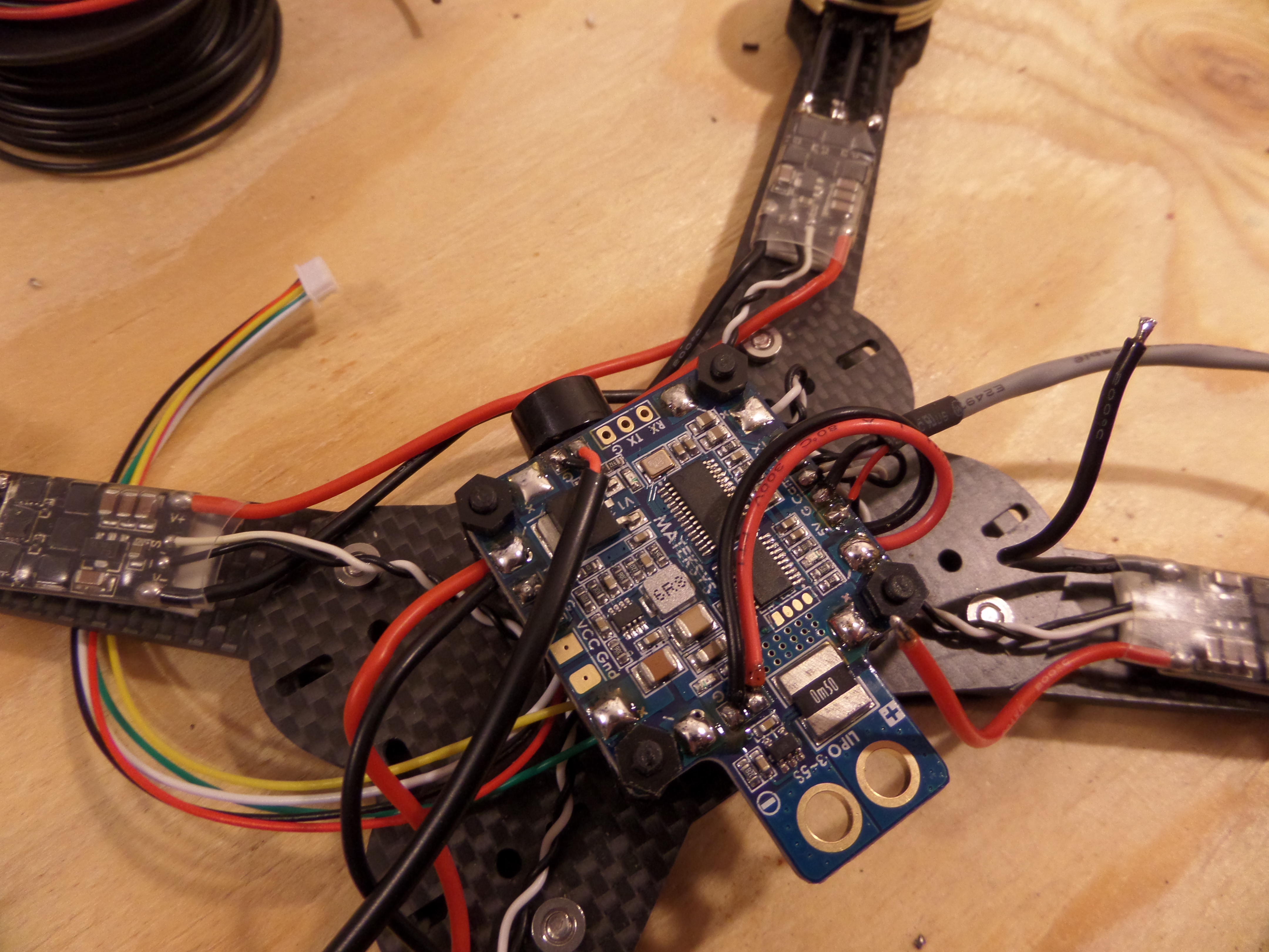
Red and black coming over the top are supplying 5V and ground to the flight controller. The red and black going into the black sheath on the left supply 12V and ground to the video transmitter. The red, black, and hardly visible white going into of the grey sheath on the right are 5V, ground, and signal for the camera. Later, after having too much wire and not enough room for the camera, I replaced that bundle with a trio of much more flexible silicon wires.
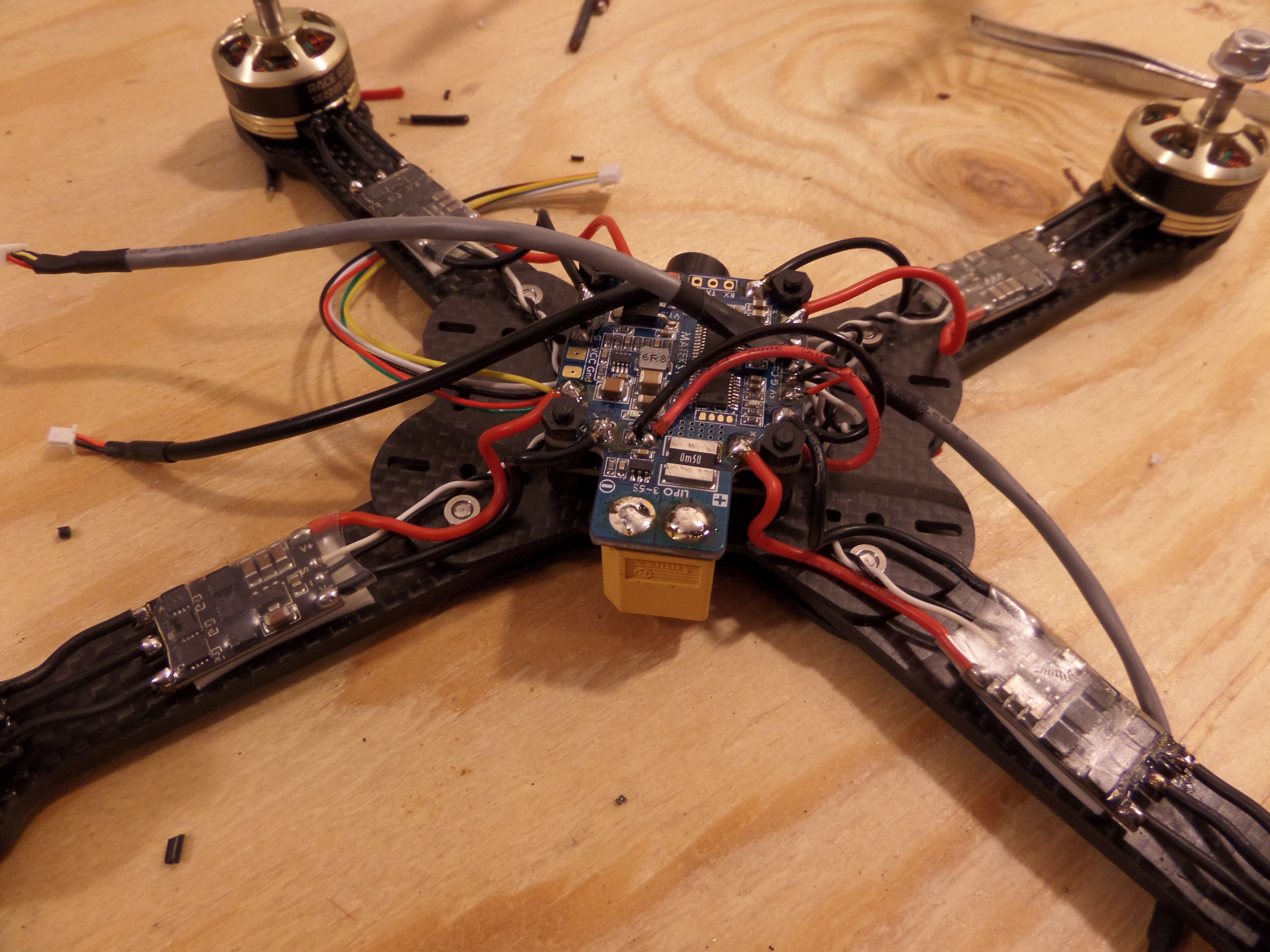
Power pathing nearly complete
Here, all the ESC power leads have been connected, and an additional grey-sheathed bundle of wires that plugs into the video transmitter to supply A/V signals. The yellow object facing downward is an XT-60 connector that the batteries will plug into.
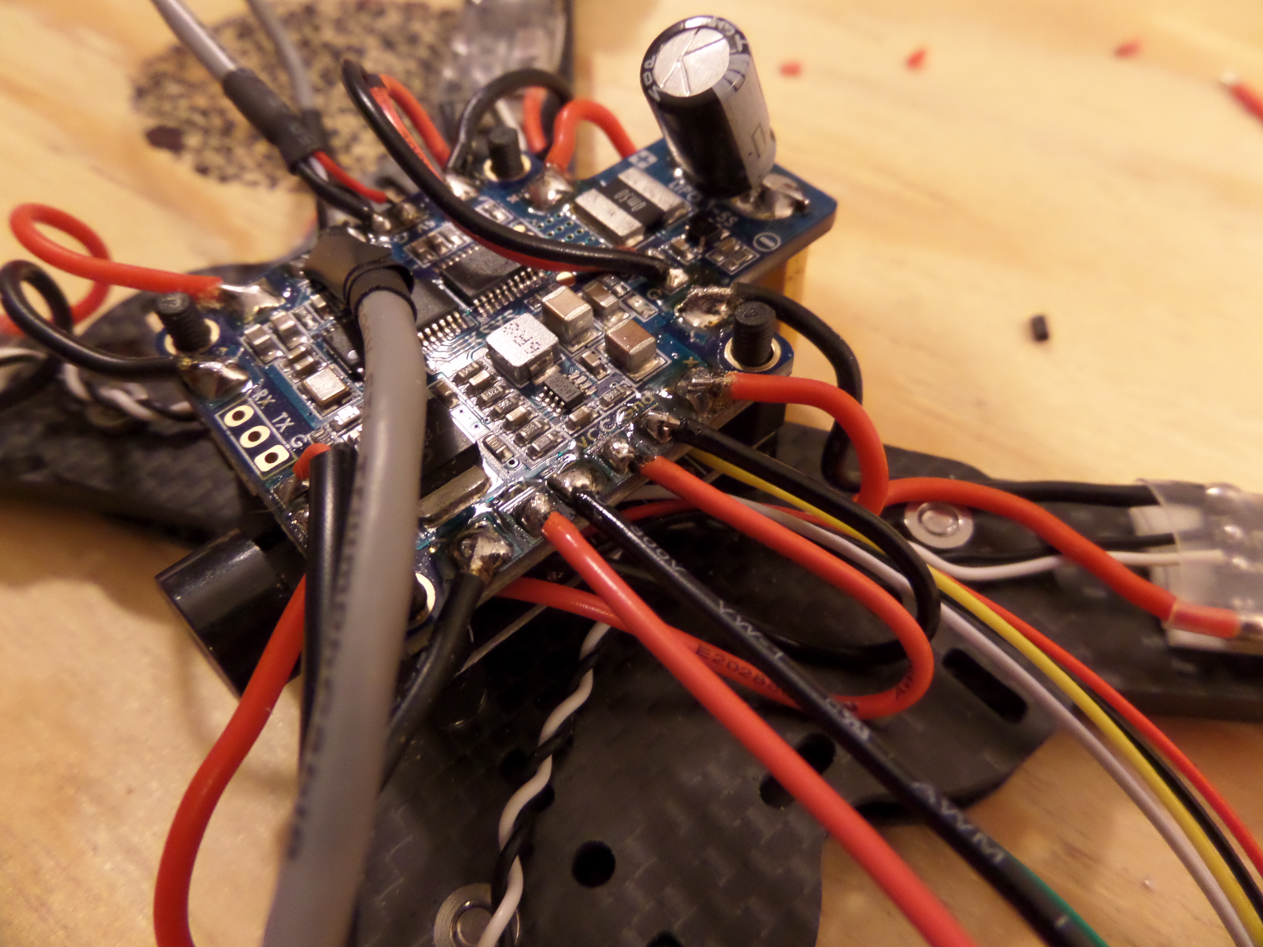
Here’s another view of things with the addition of a large capacitor soldered in parallel with the battery leads. I think it does something along the lines of smoothing out the current and reducing electrical noise…? The instructions said to add it, so there it is.

Canopy assembled
Time to build the hat. This canopy will provide some protection for the electronics I’ve already mounted, plus the radio receiver, camera, and video transmitter.
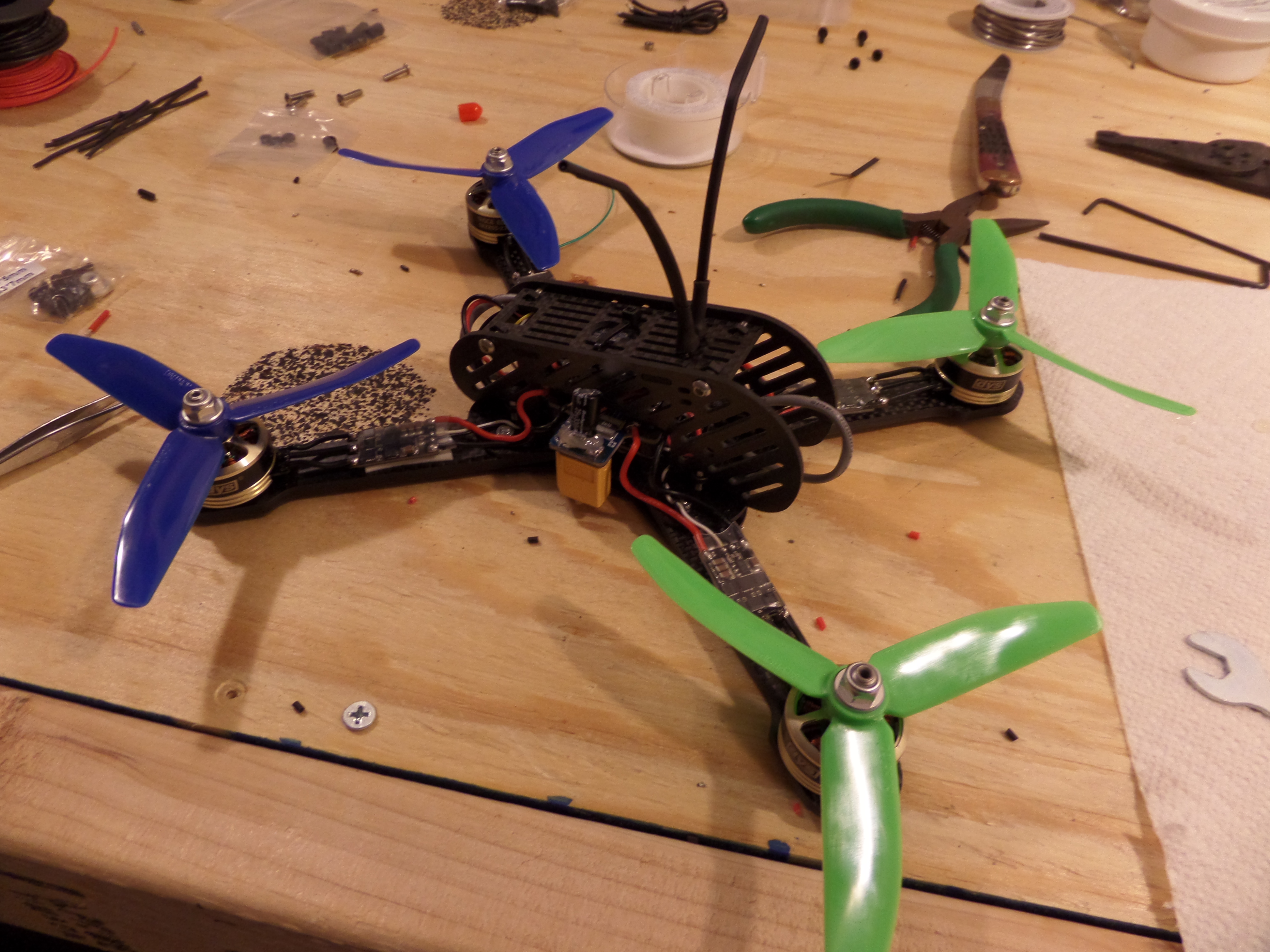
Canopy on!
And here it is assembled enough to take it out and give it some hover tests to make sure it flies ok! The camera and video transmitter are not on board yet. Sticking up are the dual radio receiver antennae. I used an old trick of sticking out two zip ties and then shrink wrapping the antennae to the zip ties. It holds them in at approximately the right angle and provides some protection as well.
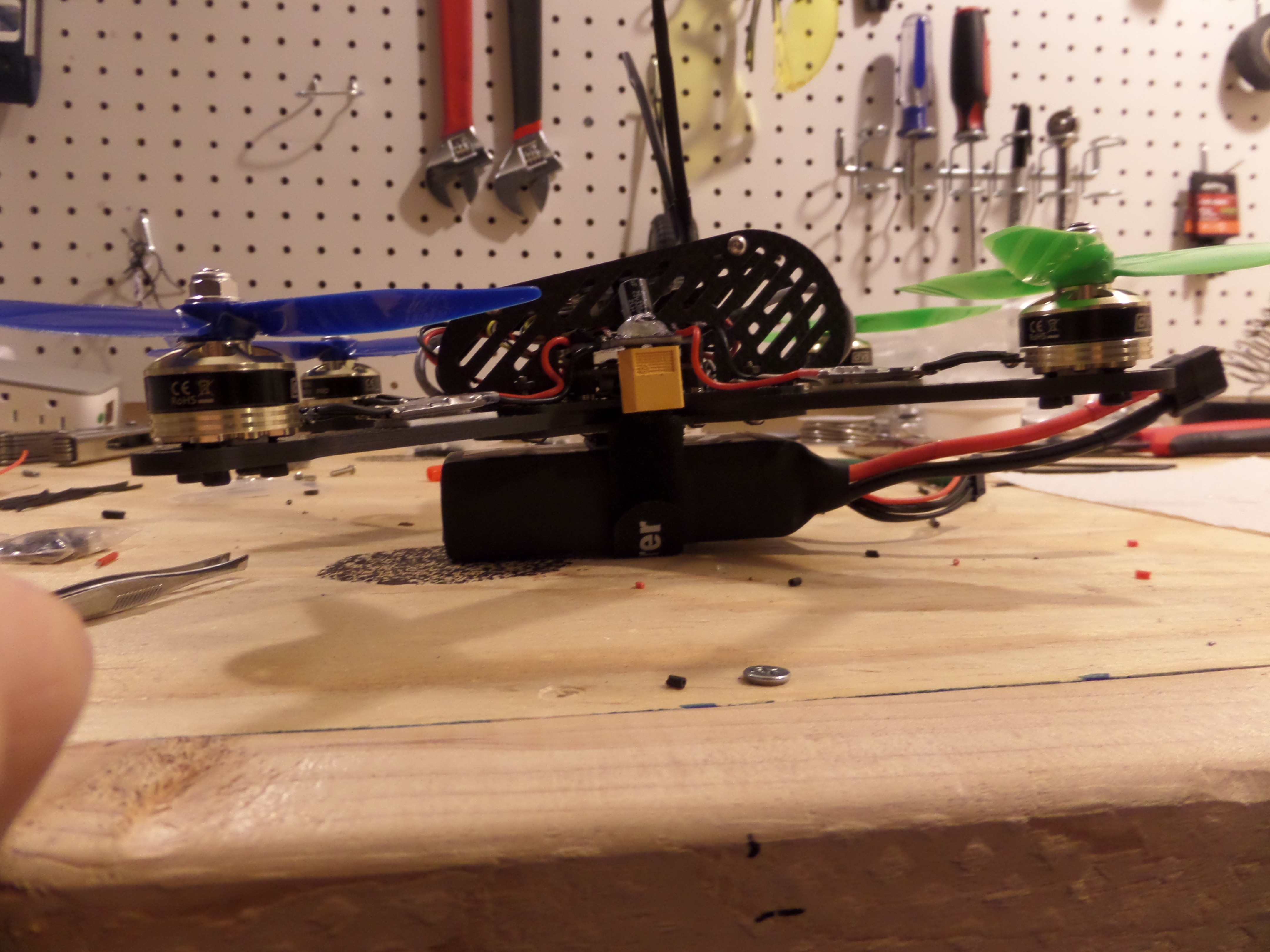
Side-on view with a battery
And here it is with a 4 cell, 1500mah battery. I’m happy to report that if hovered nicely!
Unfortunately it was much more difficult than I thought to get the video equipment properly mounted. I moved the radio receiver to the other end of the canopy and made some other slight modifications like adding a “pig tail” to the battery connector. Here it is in final “alien cyborg insect” form:
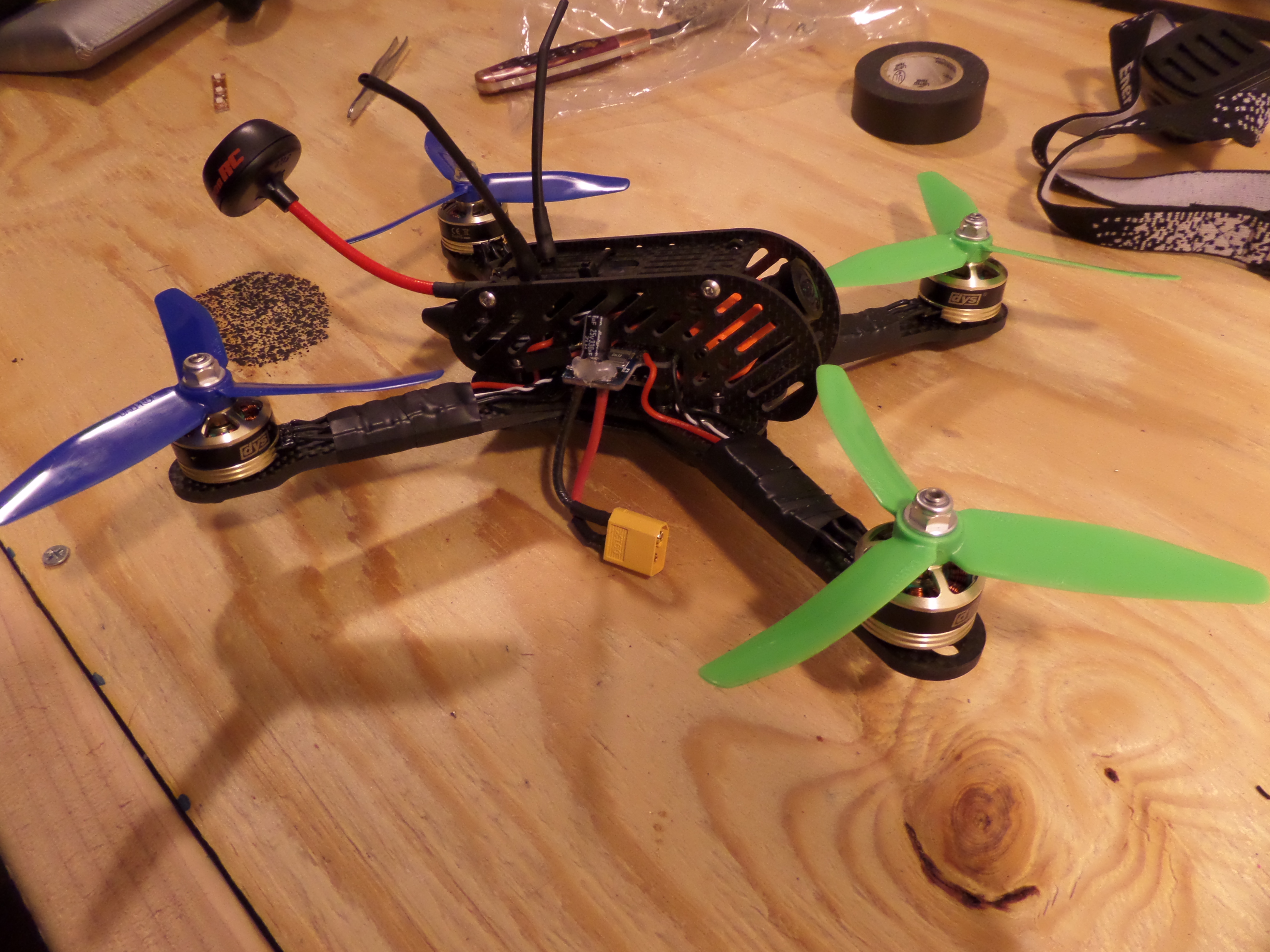
Final-ish version of the new quadcopter!
So that’s it! There will be more tinkering along the way as there always is. I want to add LEDs to the frame and use silicon wire for the pig tail. But that sort of stuff can be saved for later. For now, I must fly!
https://youtu.be/VqOoVTwxDbc